 |
 |
 |
 |
 |
 |
|
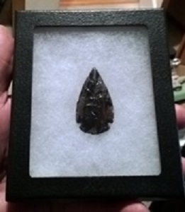
Back Lit Shadow Display Boxes By Barry Bonnell
Jim Keffer asked me to provide a tutorial for a backlit display frame that I made for an auction piece, so here it is. I've found that it’s best to use a push button that only turns the light on when it's pressed in, and goes off when the button is released. That way the battery lasts a long time. If you wanted to display your point backlit 24/7, you’d need an external plug and some controlling circuitry, but if you want to keep it simple
Materials
Display Frame/Case: I used 4.5” x 5.5” 'Riker Case' See above… Jim Keffer can quote you a price…
Jim buys the frame pictured here by the case lot and gives PSK members a good deal. You can use a shadow box if you prefer, but the synthetic cottony stuff (polyester fiberfill) in Jim’s frame is perfect for holding a point in place. And it serves double duty as an effective diffuser for the specular light from the LED. Of course, if you want to display gargantuan sized points or many points at the same time, you’ll need a bigger box, and probably more LEDs. Jim has bigger ones too, 8x10, I think.
Light Emitting Diode (LED): : 5mm Round White, 3.3 volt, Radio Shack # 2760017 (2 pack) - $2.49
<<Don’t use an incandescent bulb for an application like this because of the heat.>> The LED suggested runs cool and is perfect for this use. I got mine at Radio Shack, but there are many sources both on-line and in local areas, depending on where you live. Any 3 volt LED will work. You don’t want super bright though, just a regular white LED.
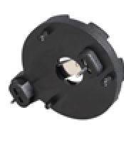
Battery Holder: CR2032 Radio Shack Catalog # 2700009 - $1.49
If you want a reliable connection to the battery, it pays to get a holder. The holder pictured here is notorious for being hard to solder. I used one for my first lighted display project and found it difficult to solder, and I’ve been soldering for 50 years. If you have flux, use it, and if you don’t, get the lugs hot enough to melt the plastic at the case. If you don’t get it hot enough, you’ll have intermittent operation. These holders are designed for use on a circuit board, but I just bend the lugs over after attaching the leads and let the cotton hold it in place. That way it’s easier to change the battery when it dies. Vetco, an electronics supplier in Bellevue, WA has a good holder that solders easily, but they are $2.40 each.
CR2032 Button Cell Battery: The ubiquitous CR2032 is easy to find and not too expensive. A pack of four at Harbor Freight costs $3, less if you have a coupon or hit a sale. This is the preferred battery for “LED Throwies” that were in vogue for a while. If you buy a lot of them, you can get them for as low as $0.25 each at cheapbatteries.com. That’s a good thing if you intend on throwing them on a roof or someplace where you can’t get them back, which is where people throw them. Once they throw them, they’re pretty much gone, and they last about a week, longer if you get one that hasn’t been on a shelf for a couple years, and a lot less if a color LED is used, often less than a day with red or yellow LEDs. For our application, on for a few seconds at a time until your guests grow thoroughly fatigued from staring at your arrowhead collections, the battery could last for a couple years.
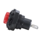
Push Button: Radio Shack $3.99. Normally Open, Momentary Closed, Single Pole, Single Throw, Radio Shack Cat. # 2750644. The picture that I borrowed from the Radio Shack web site has a red push button, but I prefer the black one. If you like red, the number is 2750646. This switch requires a ½” diameter mounting hole, and that requires a little bit of precision to fit into the ¾” deep frame used for this project. See the description below for details on how to do that. If preferred, one can find switches of much smaller diameter that would be easier to install, but not better, in my opinion. The suggested switch has the lowest profile of just about any push button I’ve seen.
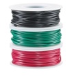
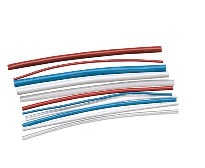
Hook-up Wire: Radio Shack 22AWG, 3 rolls of 25’, #2781224 - $8.49.
Whatever you have lying around will work. This circuit uses only a few milliamps at 3 volts.
Heat-Shrink Tubing: Radio Shack#: 2781610 $4.99.
Tools
Soldering Station: This tutorial presumes you know how to solder and that you have the soldering equipment needed. But, if you know how to do all that, you probably don’t need the tutorial. If you don’t have soldering equipment, Radio Shack has a number of inexpensive ($10 to $20) soldering pencils. They also carry a kit for $30 that will work fine for this project. There are numerous videos on YouTube regarding soldering, so you should be able to get all the knowledge you need at those sources.
Hot Glue Gun: Used to fasten the wires and components to the back of the frame. The LED needs to be secured so that it lights the correct area of the point and doesn’t shift around when people handle the display.
Spur bit: ½” for drilling the hole for the pushbutton switch. A spur bit is the best for this since the frame is made of heavy cardboard and the spurs will cut through cleanly.
Small “C” clamps: Used for accuracy in drilling the hole for the pushbutton switch.
Small pieces of scrap wood: Used for drilling a clean hole through the frame, in conjunction with the “C” clamps above.
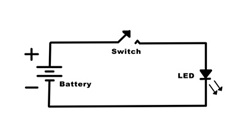
The circuit diagram looks like this:
About as simple as a circuit can get: battery, load, and an on off switch. The CR2032 battery provides 3 volts to power the LED. The push button switch closes the circuit for as long as you push the button. Releasing the button breaks the circuit and the LED turns off. The LED will only light if it’s installed with the positive lead (the long one) attached to the positive side of the battery. Standard procedure is to place the switch in the positive line. There are very good reasons for that, mostly to prevent breaking the path to ground, which would be dangerous in your house wiring, but you could put the switch in this circuit on the negative side and it wouldn’t matter at all. Good practice is to keep the switch on the “hot” line.
A quick glance notes that there is no resistor in this circuit. Most circuits with a battery and single LED recommend a small value resistor on the order of 100 ohms or less. The purpose of the resistor is to limit the current through the LED to prevent premature failure, and/or too rapid discharge of the battery. Our plain white LED has a maximum forward voltage limit of 3.6 volts and it can safely dissipate 25 milliamps, according to its datasheet. Actual measurements with a digital ohmmeter showed 11.1 milliamps flowing through our circuit with a brand new battery, well below the rated current. We’ll only turn on the circuit for a few seconds at a time and only occasionally at that, probably.
The internal resistance of the lithium button cell is discussed a lot, but for the purposes of our project, this battery has enough internal resistance to keep the current low, and it is well suited for this application. The CR2032 should last a long time without noticeable dimming of the LED.
If anyone wants to use a different color LED, it is recommended that a series resistor of at least 200 ohms be added to the circuit to prevent current from reaching observed levels as high as 107 milliamps. A red LED with a 200 ohm resistor produced a current of 6.5 milliamps, which is acceptable. Colored LEDs are usually rated at only 1.7 volts and would be overdriven by our 3 volt battery without a current limiting resistor.
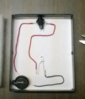
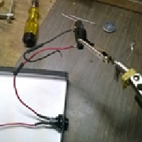
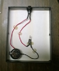
The component layout looks like this:
Circuit diagrams rarely look even remotely like the practical circuitry, but this one is pretty close. In this picture you can see the positive line in red, and the negative line in black, which are conventions. The longest lead on the LED will be soldered to the red line, and the shorter lead to the black. If you have already cut the leads on your LED, or scavenged one from a scrap circuit board, there is another way to determine the positive lead. There will be a flat surface on the plastic case on the positive side, or you can just touch the leads to the respective sides of the battery. It will only light when it is correctly oriented.
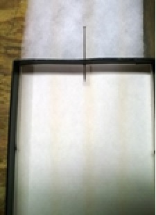
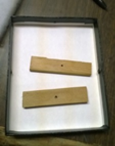
Drill the hole in the frame: The hole in the frame is a bit of a delicate procedure since the hole for this particular switch is ½” and the frame is only ¾”. It’s not too bad--if you find the center of the top wall of the frame, and push one of the pins that comes with it through your center point. The pins are installed in each side of the frame to hold pressure on the point to keep it in place.
Next, cut a pair of wood pieces to fit the wall of the frame where you intend to drill your hole. The wood is sacrificial and helps make a nice clean cut in the cardboard. Drill small holes in the centers of your pieces of wood so that you can align them with the centered pin hole that you made before.
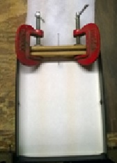
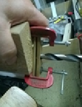
Line everything up and clamp it down. . Then back the wood pieces with the corner of a short length of 2x4 or whatever you have handy, except fingers. Drill through the centers until you cut through the cardboard. If you have a nice sharp spur bit, it won’t take more than a few seconds.
I used a hand held drill motor, and it worked perfectly.
Solder leads to the pushbutton: Don’t forget to add heat shrink before you connect things. Get in the habit, put on the heat shrink tube first thing and you won’t have to de-solder and re-solder your projects all the time. You don’t really need it on this project, but it’s good practice and will prevent short circuits that would otherwise ruin your day. A runaway lithium battery is not a good idea. There have been fires. More than one in people’s pants pockets, so I’ve heard.
Install the pushbutton switch : Do it now so you don’t forget to reinstall the switch retaining ring until after you solder to the battery holder. De-solder, re-solder, again. Believe me, I know all about it, from experience. Install the switch now.
Solder leads to the battery holder: As mentioned above, the Radio Shack CR2032 battery holder is difficult to solder. One normally expects solder lugs to be pre tinned, but these are not. Get them hot, use flux if you have it, even if you use rosin core solder
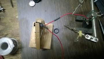
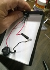
Check polarity of LED with test: In the pictured below, the LED is wired in but not soldered. Test it now, and then solder it in after you’re sure it’s oriented correctly.
Solder leads to LED: If it works when you press the button, it’s oriented correctly and you can solder it to the circuit. The leads on the LED are pre tinned, so take it easy with the heat. If you are new at soldering, leave the leads long so you don’t damage the guts of the diode.
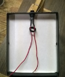
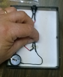
Position LED: Trial and error is the only way to know what you’ll get when the point is in place, so position the LED and cover it with the cottony stuff and press the button while holding everything down. You can put your point on there too and adjust until you get what looks good. LED’s are highly directional, if you are using the suggested one from Radio Shack, it has a viewing angle of 30 degrees, which is pretty good, but it will be lying on its side on the bottom of your box. In my installations, I bend the leads a bit to get the barrel of the LED pointing slightly upward. It won’t go far, and you don’t really need it with the cottony stuff acting as a diffuser. Just experiment around until you get the best results, then carefully lift the cotton stuff and mark the position of your LED with a pencil. Try it several times and when you are satisfied that the LED is where you want it, hot glue the leads down.
Hot Glue LED leads: Hold your LED in the position that you marked with your pencil and glue the LED leads to the back of the box. Took a while for the glue to cool enough to let go, but it was worth the wait. Be patient, hot glue sticks to your inquisitive fingertips like napalm. Don’t deny it; I know you’ve done that too… If you haven’t congratulations, you’re a better gluer than me.
Hot Glue other leads: Just a couple more beads to hold things down and you are essentially done with the wiring.
Leave the battery holder loose, so it’s easier to change the battery later. The cotton stuff will hold it in place and the lid will close with no problem, because the cotton compresses easily. No need to cut the cotton or alter it in any way.
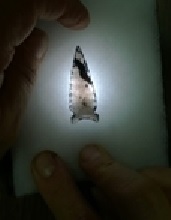
Cut out top to fit over switch : The top half of your display frame slides over the bottom half like a shoe box, but now there is a pushbutton in the way. I used my scroll saw to nibble the material away, but you could use a Dremel tool, or even a knife, if you’re careful. You could drill another ½” hole, but it’s not necessary. I used a black sharpie to cover the cut so the light color of the innards of the cardboard doesn’t show. Works good and most people will not even notice that the switch is there unless you tell them. Of course, the whole purpose of the backlight is to show off your beautiful work and the beautiful rock, so I’m sure you’ll demonstrate how it works and then hand over the display. That’s how I do it.
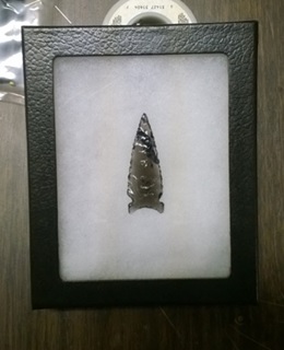
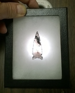
Assemble and enjoy:
|
|
©2010 J Keffer |